- Shopping, made easy.
- /
- Get the app!
Installation Steps: 1 First, you must turn off the power switch on the lower left side of the control boxThe control lever on the switch is lengthened, which can be installed with confidence, avoiding the trouble of repeated disassembly 2Remove the cotter pins at the ends of the gate arms Leaving all the wiring in place, you turn the gate arm upside down and place it on a piece of cardboard on the floor Then use the T20 tool head to remove the 14 screws Less than 2 minutes with a battery operated tool 3 You open the clamshell housing an inch or so and unplug the pin connector cable Note that the cover does not come off, but rotates open 4 A shorter T20 screw holds the board to the assembly, screw the board on, and then reinsert the connector, Make sure the orange and green cables match the markings on the board 5 After getting all this accumulated junk out, it's a good idea to put some wire or small nails in the drainage holes on the bottom, to make sure the water can drain out 6 Put the arm back together, lubricate all the pins and friction points with molybdenum grease, and then turn the power back on The control lever on the switch is lengthened, which can be installed with confidence, avoiding the trouble of repeated disassembly The product does not have a manual
 -9%
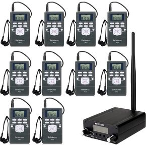
Retekess TR508 FM Transmitter for Church, Retekess PR13 FM Radio Stereo Station for Drive in Movie,Parking Lot,Home,Lights Fireworks Show, Fcc Certified
KWD 82.500
-9%
Retekess TR508 FM Transmitter for Church, Retekess PR13 FM Radio Stereo Station for Drive in Movie,Parking Lot,Home,Lights Fireworks Show, Fcc Certified
KWD 82.500
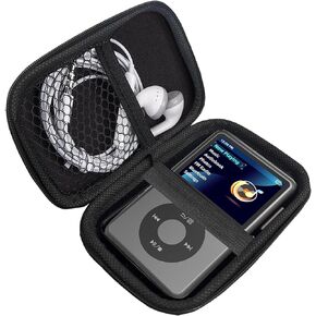 Compatible with Innioasis Y1 Case, Lamshaw Durable EVA Carrying Case, Shockproof & Lightweight Protective Cover Compatible for Innioasis Y1 Mp3 Player (Black)
KWD 6
Compatible with Innioasis Y1 Case, Lamshaw Durable EVA Carrying Case, Shockproof & Lightweight Protective Cover Compatible for Innioasis Y1 Mp3 Player (Black)
KWD 6
 MC9000 Battery Compatible with Symbol MC9000 MC909X-K MC909 Series BRTY-MC90SAB00-01 21-65587-01 7.4V 19.3WH
KWD 8.500
MC9000 Battery Compatible with Symbol MC9000 MC909X-K MC909 Series BRTY-MC90SAB00-01 21-65587-01 7.4V 19.3WH
KWD 8.500
 Compatible with MECHEN H11 Pro MP3 Player Case, Lamshaw Durable EVA Carrying Case, Shockproof & Lightweight Protective Cover Compatible for MECHEN H11 Pro 5" MP3 Player (Black)
KWD 6
Compatible with MECHEN H11 Pro MP3 Player Case, Lamshaw Durable EVA Carrying Case, Shockproof & Lightweight Protective Cover Compatible for MECHEN H11 Pro 5" MP3 Player (Black)
KWD 6


