- Shopping, made easy.
- /
- Get the app!
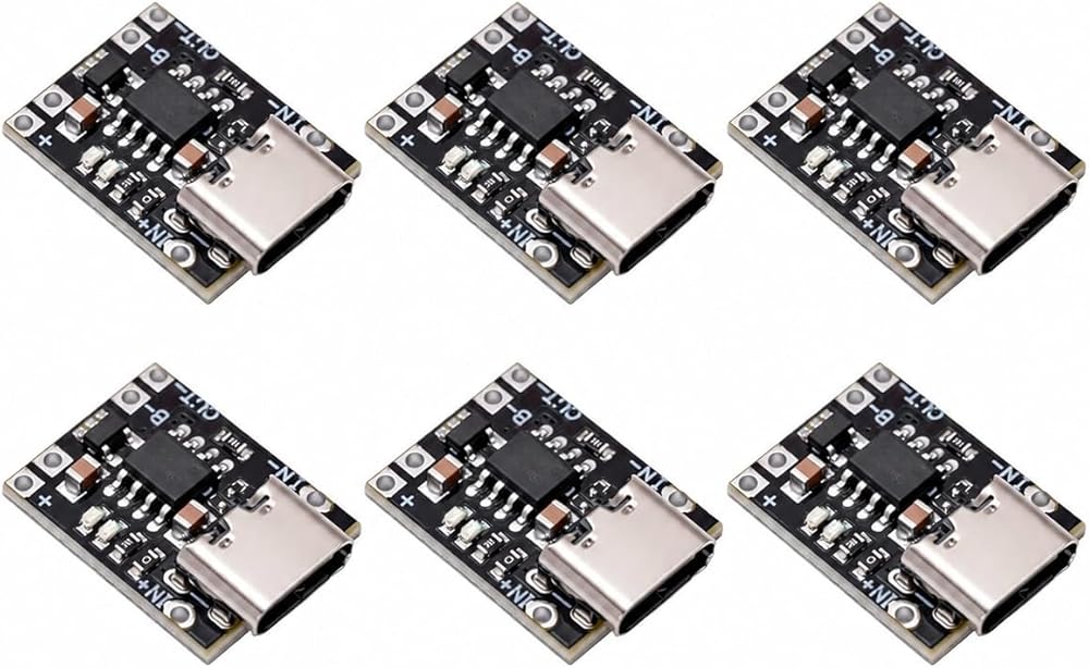
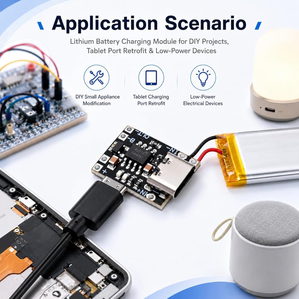
6PCS TP4057 1A 3.7V Charging Module with Type-C, Auto-Switching & Protection
Ultra-compact 14×18×5mm TP4057 module with reversible Type-C input, 1.2A max CC/CV charging, and auto-switching charge/discharge function. Designed for DIY small appliances, tablet retrofits, and low-power electronics. Not for high-power use.
Key Features
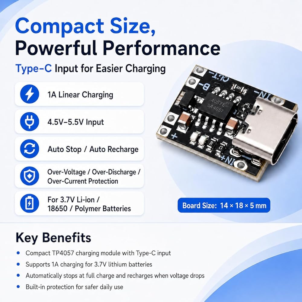
- Type-C Input (4.5–5.5V): Works with standard 5V USB chargers and phone adapters. No fast-charge protocol supported.
- 1.2A Max CC/CV Charging: 200mA trickle pre-charge below 2.9V, up to 1.2A constant current to 4.2V, stable 1.1A+ under proper power supply. Auto-terminates at 100mA cutoff when reaching final float voltage.
- Auto-Switching: Charges when external power connected; switches to discharge output when unplugged. Max 4.5W output — for low-power DIY only.
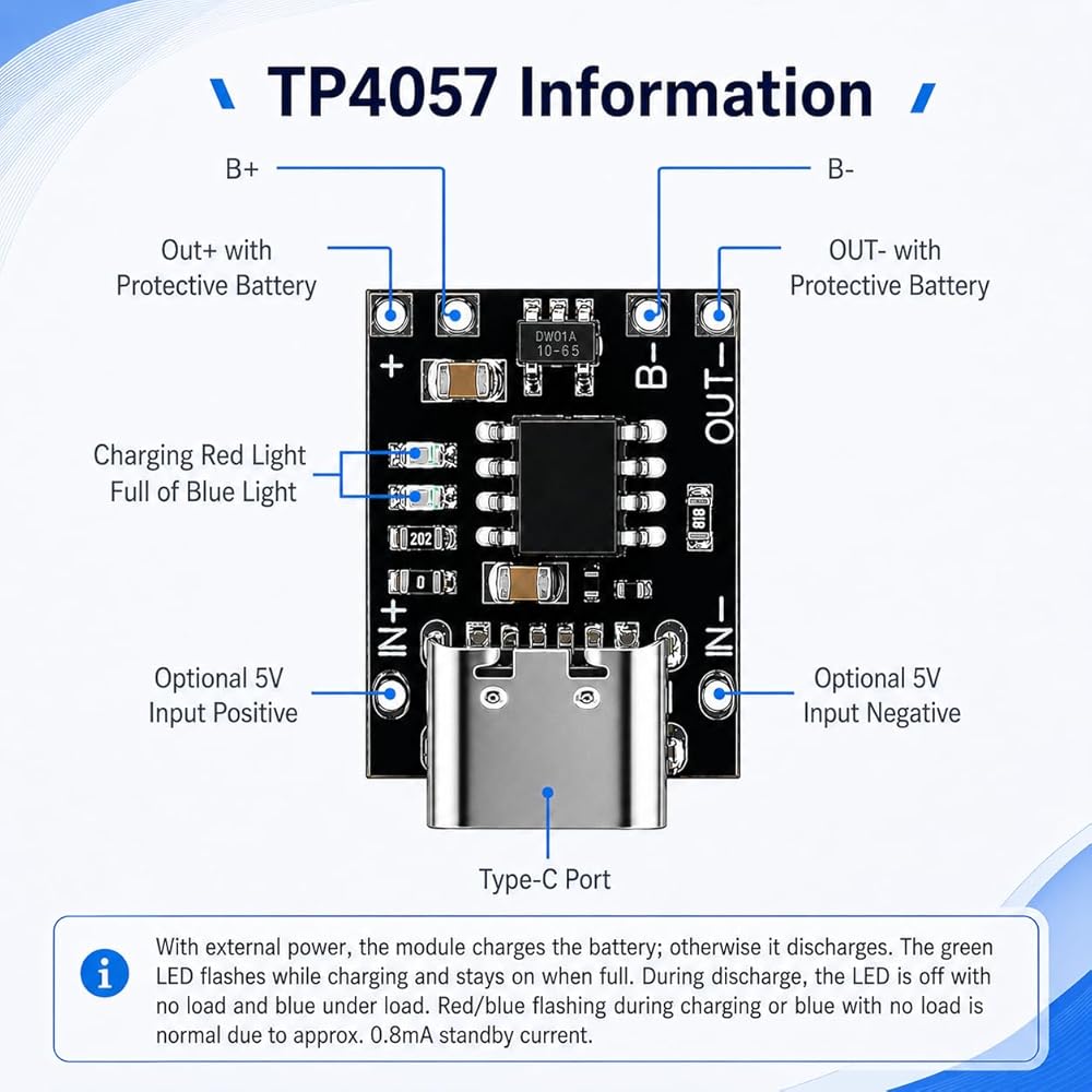
- Dual LED Indicators: Green LED flashes during charging and stays solid when fully charged at 4.2V. Blue LED illuminates during discharge output. LEDs off in no-load standby mode.
- Ultra-Low Standby: Module self-consumption only ~0.8mA, minimizing power drain when no external load is connected.
- Built-in Protection: Over-voltage, over-discharge (2.9V cutoff), over-current (4A). - Wide Compatibility: Supports various single-cell 3.7V configurations; parallel connection allowed.
Specifications
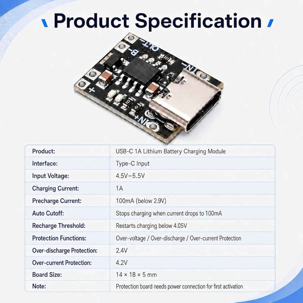
Input Voltage: 4.5–5.5V (Type-C)
Output Voltage: 4.2V
Max Charging Current: 1.2A
Stable Charging Current: 1.1A+
Pre-Charge Current: 200mA (cell voltage below 2.9V)
Termination Current: 100mA
Over-Discharge Protection: 2.9V
Over-Current Protection: 4A
Standby Current: ~0.8mA
Dimensions: 14×18×5mm (Type-C port protrudes ~1.5mm)
Package: 6PCS
LED Status Guide
- Charging: Green LED flashes
- Fully Charged: Green LED stays solid
- Discharge Output: Blue LED illuminates
- No-Load Standby: LEDs off (self-consumption ~0.8mA)
⚠️ Important Usage Notes
1. Do NOT reverse cell polarity. Reversed connection will permanently burn/damage the board.
2. Connect charger first, then cell. Plug in the Type-C charger and verify the charging LED lights up normally before connecting the power source.
3. Use thick, soldered wires only. Thin wires cannot carry sufficient current. All power connections must be soldered — do not use clips or temporary contacts.
4. Parallel only — never series. Cells may be connected in parallel for extra capacity, but series connection is strictly prohibited. For 3.7V single-cell systems only (charges to ~4.2V). 5. Not for power bank applications. This module is intended for low-power DIY projects only. Maximum output is approximately 4.5W, and it does not support any fast-charge protocols.
6. First-time activation required. The protection board IC must be activated by connecting Type-C power before attaching the cell for the first use.
Applications
DIY small appliance modification, tablet charging port upgrades, Bluetooth speakers, LED strips, Arduino/Raspberry Pi power backup, and other low-power electronics. Not suitable for high-power devices.
 -7%
Pour Over Coffee Dripper, Reusable Stainless Pour Over Coffee Maker for (1-4 Cup), Easy to Clean Paperless Pour Over Coffee Maker, Fine Mesh Coffee Strainer with Stand and Bonus Brush
KWD 6.500
-7%
Pour Over Coffee Dripper, Reusable Stainless Pour Over Coffee Maker for (1-4 Cup), Easy to Clean Paperless Pour Over Coffee Maker, Fine Mesh Coffee Strainer with Stand and Bonus Brush
KWD 6.500
 Durable 285809 Cam Agitator Repair Kit, Compatible with Whirlpool & Maytag Washers, Replaces AP3094543, 285809VP, 3951650, 3951682, 470910, AH334648, EA334648, PS334648
KWD 5
Durable 285809 Cam Agitator Repair Kit, Compatible with Whirlpool & Maytag Washers, Replaces AP3094543, 285809VP, 3951650, 3951682, 470910, AH334648, EA334648, PS334648
KWD 5
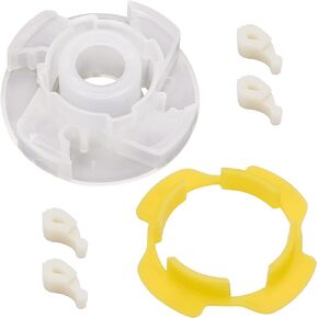
 280145 Washer Hub Kit Replacement Part, W10820039 Compatible for Whirlpool Kenmore Maytag Cabrio Bravo Oasis Washer Replaces W10118114 AP5985205 PS11723155 8545953 8545948
KWD 5.500
280145 Washer Hub Kit Replacement Part, W10820039 Compatible for Whirlpool Kenmore Maytag Cabrio Bravo Oasis Washer Replaces W10118114 AP5985205 PS11723155 8545953 8545948
KWD 5.500
 Magnetic Baskets, Black Magnetic Basket for Refrigerator, Pencil Holder, Magnetic Cup for Pens, Magnetic Pencil Holder Fine Mesh for Refrigerator, Suitable for Home, Office and School Use
KWD 4
Magnetic Baskets, Black Magnetic Basket for Refrigerator, Pencil Holder, Magnetic Cup for Pens, Magnetic Pencil Holder Fine Mesh for Refrigerator, Suitable for Home, Office and School Use
KWD 4