- Shopping, made easy.
- /
- Get the app!
The Q21-1032 Current Sensor is a Hall Effect-based transducer designed for the precise measurement of AC and DC currents. This module serves as a direct functional and mechanical replacement for standard LEM current sensors used in industrial power electronics. It provides galvanic isolation between the high-power primary circuit and the low-voltage measurement circuit, ensuring system safety and signal integrity.
Technical Operation:
This sensor operates on the closed-loop Hall Effect principle. When current flows through the primary conductor, it generates a magnetic field concentrated by the core. The Hall generator detects this field, and the internal electronics drive a secondary current to compensate for the magnetic flux, maintaining a zero-flux condition. The output signal is an accurate representation of the primary current, scaled according to the turns ratio.
Key Features:
High Linearity: Maintains accuracy across the entire measurement range, essential for precise motor control and energy metering.
Fast Response Time: Capable of tracking rapid current changes, suitable for protection circuits in inverters and drives.
Low Power Consumption: Optimized internal circuitry reduces heat generation within the control cabinet.
Noise Immunity: Shielded design minimizes interference from external electromagnetic fields (EMI/RFI).
Specifications:
Part Number: Q21-1032
Measurement Type: AC / DC / Pulse
Nominal Primary Current (IPN): [Insert Value, e.g., 100 A]
Measuring Range: Typically ±2x IPN (Check datasheet for specific overload capacity)
Secondary Output Current: [Insert Value, e.g., 50 mA or 25 mA]
Supply Voltage: [Insert Value, e.g., ±15V DC (±5%)]
Accuracy at IPN: [Insert Value, e.g., ≤ 0.5%]
Operating Temperature Range: [-40°C to +85°C]
Mounting Type: PCB Mount or Busbar Mount (via pins)
Weight: Approximately [Insert Weight] grams
Compatible Applications:
Variable Frequency Drives (VFD) and Servo Amplifiers
Uninterruptible Power Supplies (UPS)
Solar and Wind Power Inverters
Battery Management Systems (BMS) for EVs and Storage
Induction Heating and Welding Power Sources
Railway Traction Control Systems
Installation Guidelines:
Power Down: Ensure the main power supply to the control system is disconnected before installation.
Polarity Check: Verify that the supply voltage polarity (+V, 0V, -V) matches the sensor pinout. Incorrect polarity can damage the internal electronics.
Current Direction: Observe the arrow marking on the sensor housing, which indicates the direction of positive primary current flow.
Load Resistor: If using a voltage output, connect the appropriate measuring resistor (RM) across the output terminals as per the system design calculations.
Secure Mounting: Ensure the sensor is firmly mounted to prevent vibration-induced stress on the solder joints or pins.
Package Contents:
1 x Q21-1032 Current Sensor Module
Disclaimer: This product is a compatible replacement part and is not manufactured by LEM. All trademarks and part numbers are used for identification purposes only.
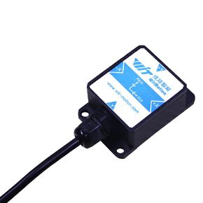 【SINVT-TTL Voltage-Output-Type Tilt Switch】High-Stability Dual-axis Analog (0-5V, 0.05° Accuracy) Secury Inclinometer, Anti-Vibration Tilt Angle Sensor (IP67 Approved) for Building/Bridge Monitoring
KWD 34
【SINVT-TTL Voltage-Output-Type Tilt Switch】High-Stability Dual-axis Analog (0-5V, 0.05° Accuracy) Secury Inclinometer, Anti-Vibration Tilt Angle Sensor (IP67 Approved) for Building/Bridge Monitoring
KWD 34
 SensComp 604142 Series 600 Instrument Grade Ultrasonic Sensor
KWD 13.500
SensComp 604142 Series 600 Instrument Grade Ultrasonic Sensor
KWD 13.500
 Mason Jar Vacuum Sealer Kit with Wide and Regular Mouth Mason Jars Lids,Vacuum Sealing Machine for Food Storage.-10 Lids and Vacuum Bag Adaptor Module
KWD 10
Mason Jar Vacuum Sealer Kit with Wide and Regular Mouth Mason Jars Lids,Vacuum Sealing Machine for Food Storage.-10 Lids and Vacuum Bag Adaptor Module
KWD 10
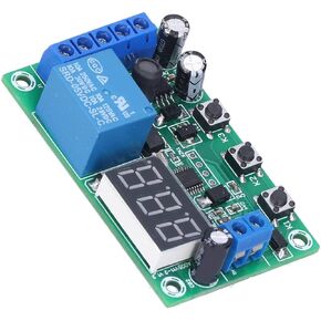 DC Current Detection Module Relay Switch Sensor Digital Display Motor Controller Digital Display with Error Calibration Function 12V
KWD 6
DC Current Detection Module Relay Switch Sensor Digital Display Motor Controller Digital Display with Error Calibration Function 12V
KWD 6
![Q21-1032 Hall Effect Current Sensor Module – Direct Replacement for LEM [Insert Amp Rating, e.g., 100A] AC/DC Transducer – Pin-Compatible for Motor Drives, Inverters & Power Supplies in Kuwait](https://cdn1.tilga.com/md/prod/3/11543/245057958.22831.jpg)
![Q21-1032 Hall Effect Current Sensor Module – Direct Replacement for LEM [Insert Amp Rating, e.g., 100A] AC/DC Transducer – Pin-Compatible for Motor Drives, Inverters & Power Supplies in Kuwait](https://cdn1.tilga.com/md/prod/3/11543/245057960.50503.jpg)
![Q21-1032 Hall Effect Current Sensor Module – Direct Replacement for LEM [Insert Amp Rating, e.g., 100A] AC/DC Transducer – Pin-Compatible for Motor Drives, Inverters & Power Supplies in Kuwait](https://cdn1.tilga.com/md/prod/3/11543/245057963.62302.jpg)
![Q21-1032 Hall Effect Current Sensor Module – Direct Replacement for LEM [Insert Amp Rating, e.g., 100A] AC/DC Transducer – Pin-Compatible for Motor Drives, Inverters & Power Supplies in Kuwait](https://cdn1.tilga.com/md/prod/3/11543/245057966.30210.jpg)
![Q21-1032 Hall Effect Current Sensor Module – Direct Replacement for LEM [Insert Amp Rating, e.g., 100A] AC/DC Transducer – Pin-Compatible for Motor Drives, Inverters & Power Supplies in Kuwait](https://cdn1.tilga.com/md/prod/3/11543/245057969.19720.jpg)
![Q21-1032 Hall Effect Current Sensor Module – Direct Replacement for LEM [Insert Amp Rating, e.g., 100A] AC/DC Transducer – Pin-Compatible for Motor Drives, Inverters & Power Supplies in Kuwait](https://cdn1.tilga.com/md/prod/3/11543/245057974.19757.jpg)
![Q21-1032 Hall Effect Current Sensor Module – Direct Replacement for LEM [Insert Amp Rating, e.g., 100A] AC/DC Transducer – Pin-Compatible for Motor Drives, Inverters & Power Supplies in Kuwait](https://cdn1.tilga.com/md/prod/3/11543/245057975.8807.jpg)