- Shopping, made easy.
- /
- Get the app!

This USB 3.1 Type-E 90-degree angled connector employs a precision PCB board structure design, comprising two core components: ① Interface end: Type-E male connector (20-pin) and female connector, strictly adhering to USB-IF specifications. The interface features dedicated locking tabs to ensure secure engagement with the motherboard socket upon insertion, preventing poor contact due to dimensional mismatch or vibration. ② Angle-adjustment mechanism: A 90-degree right-angle bent PCB substrate design. The substrate surface is coated with an insulating protective layer, while internal solder joints undergo gold plating. This reduces signal transmission loss while withstanding minor bending during installation, ensuring structural stability. The absence of redundant injection-moulded parts and screw holes results in a lighter overall structure. Compact overall dimensions (approx. 25×18×12mm) and lightweight at 12g enable cable routing and space optimisation without compromising other hardware installations, while minimising installation obstructions caused by redundant structures.
Product Name: USB 3.1 Type-E 90-Degree Right-Angle Adapter
Product Dimensions: 1.4 × 1 × 1.8 cm / 0.55 × 0.39 × 0.71 in
Connector 1: Type-E Male
Connector 2: Type-E Female
Colour: Black
Important Notes:
1. Power-off procedure to prevent hardware damage
Ensure the desktop computer is completely powered down (unplug the power supply) before installation. Never insert or remove connectors while the motherboard is powered. Doing so may cause short-circuiting or burning of the motherboard's Type-E port, or damage the internal PCB circuitry of the connector, resulting in irreversible hardware failure.
2. Align connectors properly and avoid forceful insertion/removal
When installing, first confirm the orientation of the Type-E male connector (20-pin) matches the motherboard interface pins (typically featuring anti-misinsertion design; align notches/markings). Gently push until the latch clicks into place. Never forcefully bend or press, as this may deform the PCB substrate or bend pins, impairing signal transmission or interface compatibility.
3. Allow cable slack to prevent pulling
When connecting the front-panel Type-C cable, allow 5-10cm of slack to prevent connector strain from cable tension. This avoids latch detachment or PCB solder joint loosening. After installation, gently wiggle the cable to verify connection stability and ensure no risk of poor contact.
4. Verify motherboard interface type; exclusively compatible with USB3.1 Type-E 20-pin connectors
This connector exclusively matches motherboard USB3.1 Gen 2 Type-E 20-pin interfaces (typically labelled ‘USB3.1 Type-E' or ‘USB 10G'). It is incompatible with USB3.0 Type-E (5Gbps), USB2.0 front-panel ports, or direct Type-C female connectors. Before purchasing, verify your motherboard manual or interface labelling to prevent incompatibility issues.
5. Avoid frequent insertion/removal to prolong service life
The connector PCB substrate's solder joints and locking mechanism are engineered for ‘long-term fixed use'. Repeated insertion/removal may cause latch wear or solder joint detachment. Minimise disassembly after installation. When replacing hardware, disconnect power first and gently release the latches.
Package contents: 1 x USB 3.1 Type-E 90-degree right-angle adapter
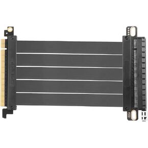 PCIE 3.0 X16 Expansion Cable, PCI-E 16x Extreme Hi-Speed Adapter Upright Card 180 Degree Connector for GPUs, WiFi, USB, Sound Cards, etc - 20 cm/7.87 in
KWD 11.500
PCIE 3.0 X16 Expansion Cable, PCI-E 16x Extreme Hi-Speed Adapter Upright Card 180 Degree Connector for GPUs, WiFi, USB, Sound Cards, etc - 20 cm/7.87 in
KWD 11.500
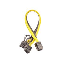 6 Pin Female to Dual 8 Pin (6+2) Male PCIe GPU Power Adapter Cable PCI Express Adapter Cable Server Supply Wiring, Mining Card Supply Line
KWD 4
6 Pin Female to Dual 8 Pin (6+2) Male PCIe GPU Power Adapter Cable PCI Express Adapter Cable Server Supply Wiring, Mining Card Supply Line
KWD 4
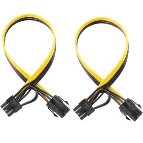 6 Pin Female to 8 Pin (6+2) Male PCI Express GPU Power Supply PCIe Adapter Cable, Computer Suitable Cable(Pack of 2)
KWD 4
6 Pin Female to 8 Pin (6+2) Male PCI Express GPU Power Supply PCIe Adapter Cable, Computer Suitable Cable(Pack of 2)
KWD 4
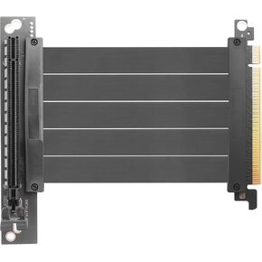 PCIE 3.0 X16 Expansion Cable, PCI-E 16x Extreme Hi-Speed Adapter Upright Card 90 Degree Connector for GPUs, WiFi, USB, Sound Cards, etc. - 24 cm/9.5 in.
KWD 11
PCIE 3.0 X16 Expansion Cable, PCI-E 16x Extreme Hi-Speed Adapter Upright Card 90 Degree Connector for GPUs, WiFi, USB, Sound Cards, etc. - 24 cm/9.5 in.
KWD 11