JESSINIE ADS1256IDB Analog to Digital Conversion Module 24 Bit ADC Data Acquisition Module Single Ended Differential Input with Programmable Digital Filter and Input Multiplexer Electronic Suite
OVERVIEW:The ADS1255 and ADS1256 are very low noise A/D converters. The ADS1255 supports one differential or two single ended inputs and has two general purpose digital I/Os. The ADS1256 supports four differential or eight single ended inputs and has four general purpose digital I/Os. Otherwise, the two units are identical and are referred to together in this data sheet as the ADS12556.
Features: The power supply voltage range is 6-60v. Current Capability comes with 1.7-A source and 2.3-A sink door driver. The product can also reduce electromagnetic interference variable speed control. The product features a guide door drive with 100% cycle support. There are 6 or 3 pwm input modes to choose from.
Internal structure: ADS1256 This device is mainly composed of analog multichannel switch (MUX), input buffer (BUF), programmable gain amplifier (PGA), fourth order modulator, programmable digital filter, clock generator, controller and serial SPI interface. Because the ADS1256 is provided with nine analog inputs, it can be configured as a 4-way differential input, an 8 way unipolar input, or a combination of differential and unipolar inputs using the analog multiway switch register.
How it works: The ADS1256 operation process is established by setting up 11 independent registers, which contain all the information to be set, such as sampling speed, analog multiplexing switch, PGA setup, I/O selection, self-calibration, etc. Table 1 shows the main register STATUS of ADS1256, including: status register, analog multichannel switch register MUX, AD control register ADCON and data speed register DRATE.
Note: When wiring the printed circuit board, the external crystal oscillator should be placed as close as possible to the ADS1256, otherwise the input amplitude will be affected. When the amplitude is too small, the amplitude can be increased by reducing the capacitance at both ends of the crystal oscillator. The capacitance range should be from 0 to 20μF, and the typical value of the access capacitance is 18pF when the crystal oscillator is 7.68MHz.
Description
The converter is comprised of a 4th-order, delta-sigma (ΔΣ) modulator followed by a programmable digital filter. A flexible input multiplexer handles differential or single-ended signals and includes circuitry to verify the integrity of the external sensor connected to the inputs. The selectable input buffer greatly increases the input impedance and the low-noise programmable gain amplifier (PGA) provides gains from 1 to 64 in binary steps. The programmable filter allows the user to optimize between a resolution of up to 23 bits noise-free and a data rate of up to 30k samples per second (SPS). The converters offer fast channel cycling for measuring multiplexed inputs and can also perform one-shot conversions that settle in just a single cycle.
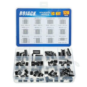 BOJACK 12 Values 120 Pcs Opamp Timer Darlington Phototcoupler LM324 LM339 ULN2003AN ULN2803APG LM358P LM386 LM393 NE5532P NE555P UA741CN JRC4558D PC817 IC Assortment Kit
KWD 8
BOJACK 12 Values 120 Pcs Opamp Timer Darlington Phototcoupler LM324 LM339 ULN2003AN ULN2803APG LM358P LM386 LM393 NE5532P NE555P UA741CN JRC4558D PC817 IC Assortment Kit
KWD 8
 Set of 10 Diode 1N5349B Diode Zener 12V 5W AXIAL
KWD 3
Set of 10 Diode 1N5349B Diode Zener 12V 5W AXIAL
KWD 3
 Bridgold 20pcs TL494CN TL494 Counter IC,PWM Controller Integrated Circuit,300 kHz 16-Pin
KWD 3
Bridgold 20pcs TL494CN TL494 Counter IC,PWM Controller Integrated Circuit,300 kHz 16-Pin
KWD 3
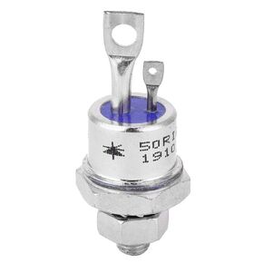 50RIA120 SCR, Thyristor, 2Pcs Silicon Controlled Rectifier, Screw Type Thyristor 50RIA120 SCR for Motor Control, Power Distribution, Schottky Diodes
KWD 6
50RIA120 SCR, Thyristor, 2Pcs Silicon Controlled Rectifier, Screw Type Thyristor 50RIA120 SCR for Motor Control, Power Distribution, Schottky Diodes
KWD 6


